160x – Flare Gas Meter
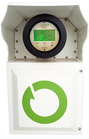
Field computer & ultrasonic transducers

The Fluenta FGM 160 has been developed to measure flare gas in pipes
where pressure, a wide range of velocity and large pipe diameter
represent a challenge. Fluenta offers world – class flare gas meters
characterized by:
- Optimal signal processing and acoustic sensors enabling flow measurement
up to 100 m/s
- Digital Signal Processing
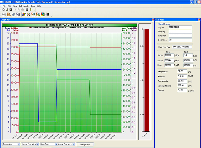
- Software based user interface (Operator Console)
- Easy and fast to install
- Field mounted flow computer
- Low maintenance costs
- Serial interface based on Modbus protocol
Application
- Measurement of flare and vent gas, characterized by a large velocity
range, low pressure and large pipe diameters
- Flare gas density calculation for gas composition indications
- Leak detection and loss calculation for mass balance in process
plants
- Accurate measurement of very low flow rates in flare and vent
systems
Advantages
- Widest velocity range on the market
- Wetted non intrusive sensor design for all pipe sizes
- High measurement accuracy throughout entire range
- Unique signal processing ensures high accuracy at low flow rate
- Fast response time
- Certified for operation in hazardous areas
- No calibration required after installation
- Rapid installation gives reduced costs
- Low maintenance
- High reliability
Installation
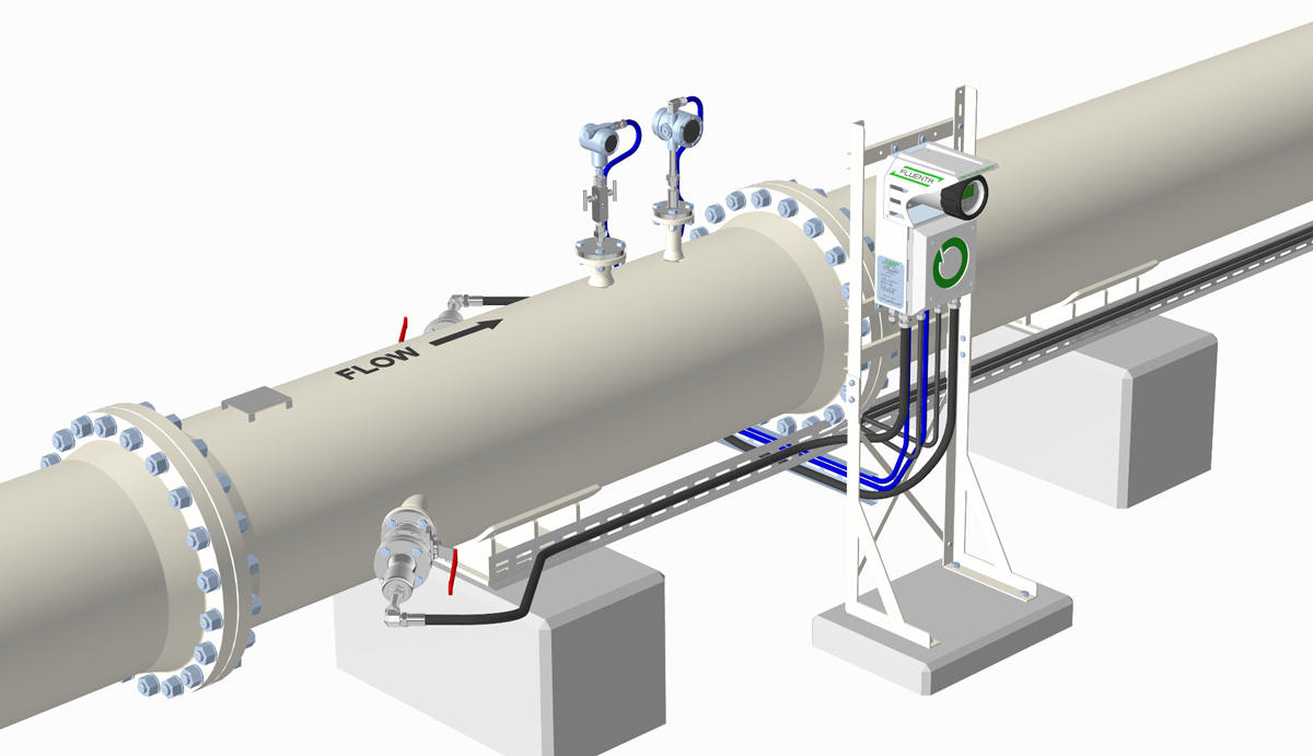
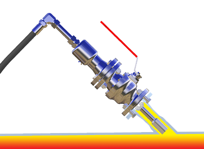
Fluenta’s FGM 160 has specially designed jigs for fast, economical and accurate mounting of transducer holders. These holders are welded onto the pipeline at an angle suitable for each different pipe size. The meter can either be delivered as a hot/cold tap version or with a prefabricated spool piece.
Operating principle
The Fluenta FGM 160 measures gas velocity based on the time–of–flight technique. The ultrasonic transducers are
mounted at an angle to the pipe. Both transducers transmit and receive pulses and the transit time is measured. When the gas is flowing in the pipe, the pulses travelling against the flow take longer to reach the opposite transducer than the pulse travelling with the flow. This time difference is used to calculate the velocity of the flowing medium.

Specifications
| Field computer |
|
| Power input: |
+24 VDC (20 – 32 VDC or 110 – 240 VAC
50/60 Hz, safe area power supply
optional) |
| Consumption: |
13 W maximum |
| Power / instrument cable : |
Standard twisted pair: RFOU(i)2-3 x 2
x 0.75mm2 |
| Dimensions: |
460 x 280 x 250mm (H x W x D) |
| Weight: |
17 kg |
| Input signals: |
Signal from transducers via std
instrument cable |
| Temperature & Pressure: |
4-20 mA or HART interface |
| Output: |
3 x 4-20 mA analog output channels, with selectable parameters.
RS 422/485 Serial Port based on Modbus protocol |
| Optional output: |
Additional 3 x 4-20 mA channels
HART
Pulse/frequency
signal |
| Electrical classification: |
Explosion proof
Ex de (ia) II C T6
Integrated Barriers |
| Ingressive Protection: |
IP 66 |
| System performance and characteristics |
| Pipe size: |
6” and larger (smaller pipe sizes
available on request) |
| Velocity range: |
0,03 – 100 m/s (0.1 – 328 ft/s) |
Uncertainty at 95% confidence level
(fully developed flow): |
±2,5 – 5% of measured value for Qv |
| Resolution: |
0.0008 m/s |
| Repeatability: |
Better than 1% |
| Turndown rangeability: |
3330 : 1 |
| Operation temperature |
-110 °C – +145 °C (transducers)
-40 °C – +85 °C (electronics)
-50 °C – +60 °C (ambient temp) |
| Operating pressure: |
0.8 – 10 Bar a |
| Design temperature: |
-150 °C – +315 °C (transducers) |
| Design pressure: |
20 Bar a (transducers) |

Operator Console
- Trend curves of all relevant measured and calculated values
- Full access to all parameters
- Log of historical measurements
- Reconfiguration and SW upload to field computer
- Integrated service console
- TCP/IP interface option for remote diagnostics and control
